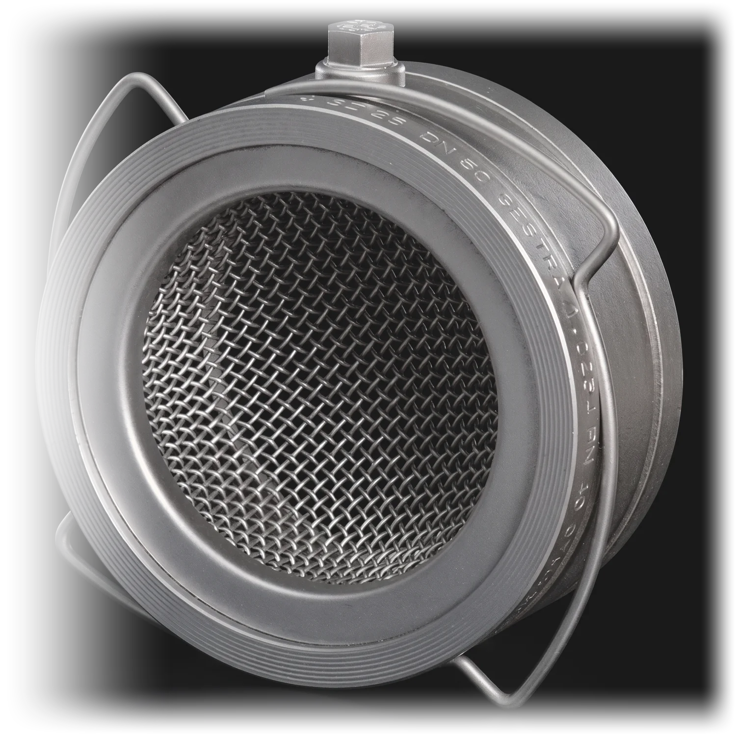
Hydrotherms
Wafer Strainer
Compact wafer-pattern filtration fitted directly between pipe flanges — no additional supports required.
Size
25 mm – 24″+
Pressure
Class 300lb
Fit
Between flanges
Compact wafer-pattern filtration fitted directly between pipe flanges — no additional supports required.
Wafer-pattern strainers are specialized filtration devices designed to remove impurities and solid particles from liquid flows in pipelines. Their distinctive wafer-style design allows for seamless integration between flanges, creating a compact and space-efficient solution. These strainers are typically sandwiched between pipe flanges, making them easy to install and maintain without the need for additional support structures.
For details on the material of construction for our fabricated strainers, and for other standards, please contact Hydrotherms.
Material certification to EN 10204, with NACE MR0175 / ISO 15156 compliance for sour service, and a full suite of additional testing available on request.
| Certification | Service Condition |
|---|---|
| Standard service | |
Supplied as standard on all Hydrotherms strainers. Certifies that pressure-wetted components meet the specified material standard, validated by the manufacturer's authorised inspection representative independent of the manufacturing department. | |
| Critical service | |
For applications demanding the highest level of assurance, certification is countersigned by an independent third-party inspector or the customer's authorised representative, providing an additional layer of verification. | |
| Sour service — H₂S present | |
Where hydrogen sulfide is present, materials comply fully with NACE MR0175 / ISO 15156 — governing hardness limits, heat treatment and alloy composition across every pressure-wetted component: body, cover, screen, bolting and sealing elements. Eliminates the risk of sulphide stress cracking (SSC), hydrogen induced cracking (HIC) and SOHIC. | |
| Sour · critical · offshore | |
The most demanding sour-service specification: independent third-party verification combined with full NACE compliance, for offshore, regulated upstream oil & gas, sour gas processing, amine treating and LNG applications. | |
Beyond the standard hydrostatic test, Hydrotherms can perform the following examinations and supply the corresponding certificates on request. Select a test to read its scope.
Every Hydrotherms strainer is hydrostatically tested to 1.5 times the maximum allowable working pressure (MAWP) prior to despatch, in accordance with ASME Section VIII requirements. Shell integrity, joint tightness, and cover seal performance are verified under sustained test pressure. A formal hydrostatic test certificate — recording test medium, test pressure, hold duration, and witnessed result — is issued as a standard deliverable with every order, with no exceptions.
Performed using compressed air or inert gas (typically nitrogen) in lieu of hydrostatic testing, where water contact is undesirable or impractical. Used to verify pressure integrity and leak-tightness. Conducted at agreed test pressures per applicable code requirements, with all safety precautions for pneumatic testing in place.
Measures the differential pressure loss across the strainer at specified flow rates and fluid conditions. Results confirm that the strainer meets the pressure drop requirements of the system design and provides a baseline for future fouling monitoring in service.
The most sensitive leak detection method available. Helium is used as a tracer gas and detected by a mass spectrometer leak detector, capable of identifying leakage rates as low as 1×10⁻⁹ mbar·l/s. Specified for critical applications including cryogenic, toxic fluid, high-vacuum, and semiconductor services.
The strainer is pressurised to destruction to determine its actual burst pressure and failure mode. Confirms that the design safety margin exceeds the minimum required factor and validates finite element analysis (FEA) predictions. Typically performed on prototype or first-article samples.
Simulates pressure surge (water hammer) conditions to verify that the strainer body, cover, and screen withstand transient peak pressure events without deformation or leakage. Critical for pump discharge and fast-acting valve installations.
X-ray or gamma-ray examination of welds and castings to detect internal discontinuities including porosity, slag inclusions, lack of fusion, and cracks — defects that are invisible to surface examination. Conducted and reported in accordance with ASME Section V and the applicable acceptance criteria of ASME Section VIII.
Detects surface and near-surface discontinuities in ferromagnetic materials by applying magnetic flux and iron particle media. Reveals cracks, laps, seams, and inclusions that could compromise the integrity of weld joints or base material. Performed to ASME Section V, Article 7.
A liquid penetrant is applied to the cleaned surface, drawn into surface-breaking defects by capillary action, and subsequently revealed by a developer. Applicable to all non-porous materials including stainless steel, duplex, and nickel alloys where magnetic particle testing is not feasible. Performed to ASME Section V, Article 6.
High-frequency sound waves are used to detect internal and surface flaws in welds and base material, and to measure wall thickness. Particularly effective for detecting planar defects such as lack of fusion and cracks. Also used for thickness measurement on castings and formed components where dimensional access is restricted.
A chemical surface test used to detect free iron contamination on stainless steel components. A ferroxyl reagent solution is applied to the surface; any free iron deposits turn blue, confirming the presence of contamination that could initiate corrosion in service. Mandatory for many food, pharmaceutical, and high-purity stainless steel applications.
Tensile test specimens are machined from the same heat of material as the strainer components and tested to determine yield strength, ultimate tensile strength, and elongation. Results confirm that the material meets the minimum mechanical property requirements of the specified material standard and design code.
Brinell, Rockwell, or Vickers hardness measurements are taken on base material, weld metal, and heat-affected zones. Hardness testing is mandatory for all NACE MR0175 / ISO 15156 applications to confirm that material hardness does not exceed the limits above which sulphide stress cracking can occur. Also used to verify post-weld heat treatment (PWHT) effectiveness.
Charpy V-notch impact tests are performed at the minimum design temperature (MDT) to verify that materials possess adequate notch toughness and resistance to brittle fracture. Required by ASME Section VIII for low-temperature carbon steel (LTCS) applications and for all materials used below −29°C. Results must meet the minimum absorbed energy values specified by the design code.
Electrical resistance strain gauges are bonded to the strainer body at critical stress locations. Actual surface strains are measured under defined pressure and load conditions and compared against design predictions. Used to validate FEA models and confirm structural adequacy for non-standard geometries or extreme service conditions.
A brittle lacquer coating is applied to the component surface. Under applied load, the coating cracks at yield locations, visually mapping the strain distribution and identifying stress concentration areas. Provides a full-field indication of stress patterns that complements strain-gauge point measurements.
Pressure and leak testing performed at cryogenic temperatures — typically down to −196°C for LNG and liquid nitrogen service. Confirms that all materials, welds, seals, and fasteners maintain their mechanical properties and leak-tight integrity at the extreme low temperatures encountered in LNG, cryogenic processing, and cold box applications.
Evaluates structural integrity under sudden mechanical shock loads — including those resulting from water hammer, seismic events, or transportation impacts. Required for naval, offshore, and seismically active installation sites.
Subjects the strainer to defined vibration profiles to verify that connections, fasteners, and screen elements remain secure under continuous operational vibration. Particularly relevant for strainers installed on or near rotating equipment such as pumps, compressors, and turbines.
Functional operation tests to verify that all moving components — including covers, quick-opening closures, diverter valves (duplex strainers), and access flanges — operate correctly, smoothly, and within the required torque or force limits. Confirms ease of maintenance and correct mechanical assembly prior to despatch.
Tensile or bent-beam specimens are exposed to a defined H₂S-saturated test solution at controlled stress levels to evaluate susceptibility to sulphide stress cracking (SSC) — a form of hydrogen embrittlement that affects high-strength steels in sour environments. Performed in accordance with NACE TM0177 methods. Required on critical sour service components to provide independent confirmation of SSC resistance beyond hardness compliance alone.
Plate specimens are immersed in a standard H₂S test solution per NACE TM0284 to evaluate susceptibility to hydrogen induced cracking (HIC) — step-wise cracking caused by hydrogen diffusion into the steel microstructure. Crack length ratio (CLR), crack thickness ratio (CTR), and crack sensitivity ratio (CSR) are measured and reported. Required for carbon steel pressure vessels and piping components in wet sour service per NACE MR0175 / ISO 15156.
The Hydrotherms wafer strainer general catalogue — overview, size and range, materials, options, testing and certification. PDF, 8 pages. The detailed datasheet follows shortly.
DownloadInstallation between flanges, screen access and cleaning procedure, and recommended maintenance intervals.
DownloadFind out how Hydrotherms Y strainers and accessories can meet your project specifications and deliver reliable performance across your operations.
Contact SalesFor all other questions — product specifications, lead times, technical documentation, or general information — please reach out and our team will respond promptly.
Contact UsA wafer-pattern strainer is a filtration device that removes impurities and solid particles from liquid flows in pipelines. Its wafer-style body is sandwiched directly between two pipe flanges, creating a compact, space-efficient installation.
It is installed between existing pipe flanges. Because the body is held by the flange bolting, no additional support structures or special tools are required, which makes installation and maintenance straightforward.
Hydrotherms wafer strainers are supplied flanged from 25 mm to 24″+ (600 mm+), with a maximum pressure rating of Class 300 lb. Contact Hydrotherms for other pressure ratings.
They are manufactured to match all international standards including BS 10, BS 4504, ANSI B16.5, ANSI B16.47 Series A (MSS SP 44) and Series B (API 605), AWWA C207 Class D & E, ASME, EN 1092, DIN, NFE, JIS and ISO. Consult Hydrotherms for other standards.
Carbon steel (A216 WCB, A352 LCB), carbon moly and chrome-moly grades (A217 WC1, WC6, WC9, C5, C12), stainless steels (A351 CF8, CF8C, CF8M), 3½ Ni (A352 LC3), duplex and super duplex, aluminium bronze, Inconel, Monel, Hastelloy B and C, titanium, nickel and Alloy 20 (CN7M, CN3MCu).
Yes. Magnetic inserts or magnetic screens can be added to the strainer element to capture ferrous particles carried in the process fluid.