Featured Solutions Y Strainer Simplex Basket Strainer Duplex Strainer Tee Strainer Automatic Strainer Conical Strainer Suction Diffuser Wafer Strainer Accessories Company Resources Contact us
Continuous-Flow / Duplex Straining
Solution 04

Duplex Strainers for
Continuous Flow

Cleaning the screen without stopping the process — designed in at the start, not retrofitted after the first shutdown.

Purpose
Zero-downtime cleaning
Typical Types
Duplex · Automatic
Key Element
Changeover valve
Design Stage
Specify early
02 — Overview

What continuous-flow straining means

A single-chamber strainer has to be isolated to be cleaned. On a batch process or a line with spare capacity that is a manageable interruption. On continuous duty it is not, and the strainer becomes the reason the plant stops.

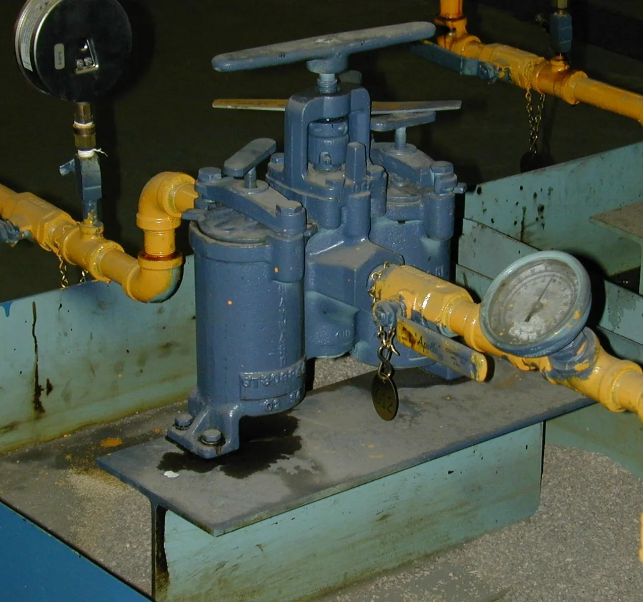
Two arrangements solve it. A duplex strainer places two chambers in parallel with a changeover valve, so flow is diverted to one side while the other is isolated, drained, opened and cleaned. An automatic self-cleaning strainer keeps a single chamber but cleans the screen in place under flow, discharging debris through a purge connection.

03 — The Engineering Challenge

Why this has to be decided early

01 / Downtime

Unplanned Interruption

A single-chamber strainer on continuous duty will eventually force a shutdown to clean — usually when the dirt load is highest and the process can least afford it.

02 / Retrofit

Space & Cost Later

A duplex body, its changeover valve and its access clearance take considerably more space than a single chamber. Adding them after the piping is built is expensive and sometimes not possible.

03 / Changeover

Transfer Conditions

The changeover itself has to be considered — transferring flow between chambers should not expose the process to a pressure transient or admit air into a liquid line.

04 — Our Engineering Solution

Two chambers, or one that cleans itself

A duplex arrangement is sized so that each chamber alone carries the full design flow within the allowable pressure drop, because that is the operating condition during cleaning. Each chamber needs its own drain and vent so it can be depressurised and drained before the cover is opened, and the changeover valve is selected for tight isolation of the offline chamber.

An automatic self-cleaning strainer suits continuous duty with a steady or high solids load, cleaning on a differential pressure set point, on a timer, or both. It removes the manual cleaning task entirely, at the cost of a powered actuator, a control interface and a purge line that has to be routed and disposed of.

05 — How We Engineer the Solution

The selection sequence

Six governing inputs, one evaluation, four engineered outputs. The defining question is what the process can tolerate during cleaning, and that answer drives the rest.

PROCESS INPUTSEVALUATIONENGINEERED OUTPUTFlow rateLine sizeSolids loadingAllowable pressure dropAcceptable downtimeUtilities availableCONTINUOUSDUTYSELECTIONDuplex or automaticChamber & screen sizingChangeover / purge arrangementDrain & vent provision

Each duplex chamber is sized for full design flow on its own, because single-chamber operation is the condition during cleaning — not an upset case.

06 — Strainer Selection

Which configuration fits?

RequirementPossible Solution
Manual cleaning acceptable, flow must not stopDuplex Strainer
No manual intervention available or practicalAutomatic Strainer
High or variable solids loading in continuous dutyAutomatic Strainer
Remote or unattended installationAutomatic Strainer with monitoring

Duplex suits continuous duty where manual cleaning is available but downtime is not. Automatic suits continuous duty where manual intervention itself is impractical, and requires power, a control interface and a purge route.

07 — Design Parameters

What we need to size it

For continuous-duty selection we also need to know what the process can tolerate during cleaning and what utilities are available at the location.

Fluid / Service
Process medium
Line Size
Nominal bore
Flow Rate
Design / normal
Operating & Design Pressure
Barg / psig
Operating & Design Temperature
°C / °F
Allowable Pressure Drop
Across strainer
Required Filtration Rating
Mesh / perforation / micron
Material Requirement
Fluid compatibility
End Connection
FLG / BW / SW / SCR
Installation Orientation
Piping layout
Drain / Vent Requirement
Chamber drain-down
Maintenance Philosophy
Access & downtime
Solids Loading
Concentration & type
Utilities at Location
Power / air / purge route
08 — Typical Applications

Where this is used

Continuous process linesCooling water circulationSeawater and intake filtrationBoiler feed and condensate systemsRemote or unattended installationsHigh solids-loading duties

What this achieves

Allows screen cleaning without interrupting process flow
Removes the strainer as a cause of unplanned shutdown
Holds pressure drop within a defined operating band
Supports unattended operation where automatic cleaning is specified
Provides a planned, safe route for draining and opening a chamber
10 — Materials & Installation

Selected for the application

Duplex bodies are supplied cast or fabricated depending on size and pressure class, in carbon steel, low-temperature carbon steel, stainless steel, duplex, super duplex and nickel alloys. Baskets, changeover valve internals and sealing elements are selected for the same service conditions as the body.

Access, drains and the purge line

Allow clearance above or beside each chamber to withdraw the basket, and specify davit arms or hinged covers on larger sizes where manual handling is impractical. Every chamber needs a drain and a vent. On an automatic strainer, the purge discharge has to be routed, collected and disposed of in a way the site can actually accommodate — plan it with the piping, not afterwards.

11 — FAQ

Common selection questions

A duplex strainer has two chambers and a changeover valve; flow is diverted to one while the other is cleaned by hand. An automatic self-cleaning strainer has one chamber and cleans the screen in place under flow, discharging debris through a purge valve. Duplex removes the downtime; automatic removes the manual task as well.

Each chamber is sized to carry the full design flow within the allowable pressure drop on its own, because single-chamber operation is exactly what happens during cleaning. Sizing each chamber for half the flow would exceed the pressure drop limit whenever the strainer is cleaned.

A properly selected changeover valve transfers flow between chambers without shutting the line. The transfer still needs consideration — venting and filling the standby chamber before changeover avoids admitting air into a liquid system.

Rarely without significant rework. The body, changeover valve and access clearance need considerably more space than a single chamber, so it is far cheaper to specify it during piping design than to retrofit it.

A power supply for the actuator, a control input — differential pressure switch, timer, or both — and a routed purge discharge with somewhere for the backwash effluent to go. These are site requirements, not options.

13 — Technical Enquiry

Request engineering assistance